Intel 8087 microcode: how the chip adds and subtracts floats
In 1980 Intel introduced the 8087, a chip that made floating-point operations much faster in the IBM PC and other systems. The article's author says it sped up addition by a factor of almost 100 compared with the 8086 processor, and complicated operations by even more. The piece examines the chip's microcode and circuitry to explain exactly how addition and subtraction work, including the many special cases for infinities and other special values.
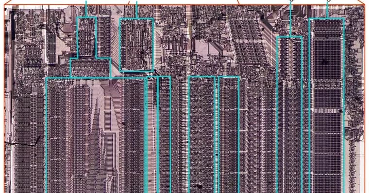
To see the circuitry, the author popped the lid off a chip with a chisel and photographed the die through a microscope. The microcode ROM is the large rectangular region in the centre of the die and holds 1648 micro-instructions. The bottom half of the chip is the datapath, which performs calculations on 80-bit values. The parts that matter for addition are the integer adder in the middle (fed by the B register on one side and by a temporary or stack register on the other, with its output going to the sum register), the shifter, the leading-zero circuitry that counts zero bits or bytes on the left of a value, and the exponent converter, which detects overflow and underflow. The shifter takes up a lot of die space because it can shift a value by an arbitrary number of bits quickly.
The article first reviews floating-point basics. A number is sign × significand × 2^exponent, where the significand has the form 1.bbb. Binary 1.1 is 1.5, binary 1.0011 is 1.1875, and 1.1 (binary) × 2^8 is 384. Addition needs the binary points aligned, so the number with the smaller exponent is shifted right until the exponents match; the significands are then added as integers, and the result is normalized so it starts with a 1 bit. In the worked example 13.5+3.5, the second argument is shifted two positions right, the sum overflows into an extra left-hand bit, and the result is shifted one position right with the exponent incremented by 1. Subtraction adds complications: the result can be positive, negative or zero, and it can be orders of magnitude smaller than the inputs. In the example 8-7.5, normalization needs a four-bit left shift and the exponent drops by 4. A negative result means the significand is made positive and the sign flipped. A zero result cannot be normalized, so +0 or -0 is returned as appropriate.
Internally the 8087 stores numbers in an 80-bit 'temporary real' format: a sign bit, a 15-bit exponent and a 64-bit significand. The exponent carries a bias of 16383, so an exponent of 1 is stored as 0x4000 and an exponent of -16 as 0x3fef. Eight registers form a stack, and each value carries a tag: zero, valid, special (infinity, NaN or denormalized) or empty. The empty tag lets the chip detect stack underflow and overflow. Internal temporary registers tmpA and tmpB are 80 bits plus two tag bits, while tmpC has no sign, exponent or tag and a 68-bit significand: one extra bit against overflow and three low-order rounding bits (guard, round and sticky). Each 16-bit micro-instruction does one low-level operation, such as moving data between registers, a conditional jump, a subroutine call or a return. The 69-bit adder needs two micro-instructions per addition: the first picks the first argument and options such as carry and rounding (subtraction complements the second argument), and the second moves the result from the sum register to its destination. The second argument always comes from the B register, which the author notes is unrelated to tmpB. The shifter also works in two steps, and shifts a 68-bit value left or right by any amount.
Almost all 8087 operations are implemented in microcode. Addition, subtraction, multiplication and division all begin at the same code at decimal address #0001, which moves the two arguments (normally from the stack registers) into tmpA and tmpB. It then calls a micro-subroutine for the specific operation. A small ROM table holds jump and call targets, and target 0 is special: it holds three different addresses for multiplication, division and addition/subtraction, through special-case circuitry in the ROM that the author calls a weird, hacky optimization.
The addition/subtraction routine starts at #0232. It first handles the zero cases 0+0 and 0-0. It then subtracts the exponents; if the first argument has the smaller exponent, the arguments are swapped so the larger one comes first, and a 'sign latch' that tracks the result sign is toggled (at #0244) if the swap would change the sign. The smaller operand is then shifted to match exponents using a CREATE_DENORM call, and an exponent adjustment is stored in tmpB. For subtraction the microcode computes tmpA minus tmpB; if the result is negative it negates the fraction and toggles the sign latch, and if the sum register is zero it jumps to the zero-result code, which returns +0, or -0 under some rounding modes. For addition at #0269 it adds the fractions, checks for overflow in bit 64 of the sum register, and if set shifts right one bit and increments the exponent adjustment. The text available ends partway through the microcode listing, during the subtraction path's rounding-bit shifts.
Key facts
- Intel introduced the 8087 in 1980; the article's author says it sped up addition by almost 100 times over the 8086, and complicated operations by even more.
- The author decapped a chip with a chisel and photographed the die; the microcode ROM holds 1648 micro-instructions and the bottom half of the chip is an 80-bit datapath.
- Internally numbers use an 80-bit 'temporary real' format (sign bit, 15-bit exponent with a 16383 bias, 64-bit significand), and a 69-bit integer adder does the arithmetic in two micro-instructions per addition.
- The addition/subtraction micro-subroutine starts at address #0232: it handles 0+0 and 0-0, subtracts exponents, swaps arguments if needed, aligns the smaller one with the shifter, then adds or subtracts the significands.
- Subtraction needs extra care: negative results are negated with the sign flipped, zero results return +0 or -0, and large left shifts may be needed to normalize.
Why it matters
The 8087 is the coprocessor that made floating-point maths much faster in the IBM PC and similar systems, and the article shows how that speed was built. The author says addition ran almost 100 times faster than on the 8086 alone. The explanation is concrete: a dedicated 69-bit adder, a large shifter, leading-zero counting and an exponent converter, all steered by a 1648-entry microcode ROM. It also shows the chip's quirks, such as the ROM table entry that returns different addresses for multiplication, division and addition/subtraction.
Who it affects
Readers interested in computer history, processor design, microcode and floating-point arithmetic. It also suits anyone who wants to see how a classic x87-era chip handles special values such as zero, infinity and denormalized numbers, which the 8087 tags separately in its register stack.
How to use it
It is a reading and learning resource, not a tool. The worked examples (13.5+3.5 for addition, 8-7.5 for subtraction) are a good way to follow the steps of aligning, adding or subtracting, and normalizing before reading the microcode listing. The listing itself is annotated, with each micro-instruction at a numbered address such as #0232, so it can be traced step by step alongside the prose.
How solid is it
The article is first-hand work: the author opened a chip, photographed the die and read the microcode. The retelling covers the part of the routine shown in the available text, which runs from the start of the subroutine to part of the way through the subtraction and rounding code; the later steps are not visible there. The roughly 100× speedup figure is stated for addition only, and the source gives no benchmark details behind it.
Risks and caveats
The speedup figure for addition is the author's own statement, without clock speed, benchmark or method given. The article explicitly leaves out loading operands from memory. Only the part of the addition/subtraction routine in the available text is described here, so the final normalization, rounding and special-value handling steps are not covered. Obtaining the die images meant destroying a chip with a chisel, so this is not a casual experiment.
“When you're designing the chip, you can do weird, hacky optimizations like this if you want.”
— The article's author, on the 8087's special-case ROM address table